
Building a ship's stove
BUILDING A SHIP’S STOVE
Allan Yedlinsky
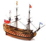
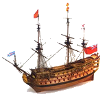
A fun project and good practice in the minutiae that comes in building a ship model is building the galley stove. The British stoves were very similar from vessel to vessel in the second half of the 18th century in both design and materials. The stove in this tutorial was taken from the design shown in the Anatomy of a Ship series volume on the Pandora and David Antscherl’s The Fully Framed Model so will be appropriate for those building the Triton or similar vessels. Larger vessels used the same basic design from what I have seen in various books. There are drawings of these stoves in many good ship-modeling books in addition to the two mentioned above. You will need the drawings to size all of the parts, as I have not included any drawings in this tutorial. Keep in mind that the stove may sit between a pair of bitt standards on some vessels so be careful that the stove will fit properly on your ship. Get the over all dimensions and go from there. Making the stove 1/8” smaller will not change the construction, but 1/8” over may not fit between the bitt standards. The largest item is the stove base plate, which is the last item to install. I make mine first to check it against the dimensions of the bitt standards if they are a factor.
I used wood, brass rod and mini nails, stiff card stock materials (photo paper) and a piece of heavy black thread. Other building materials include aliphatic glue, silver solder, Blackin It, and “Grime” colored paint.
Start with the stove base. Note that it is not a true box in that part of the fore and aft ends of the base slope inward. I did not construct the vanes and firebox found inside the base and stack as they were totally enclosed. Maybe someone will want to do this and show the stove in a cut away fashion so all the inside parts will be
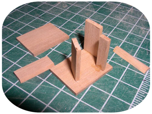
Photo 1 shows the pieces of the stove base. Some may chose to make this of metal, but I found it easier to use wood, boxwood in this case. These were glued together with ordinary aliphatic carpenter’s glue.
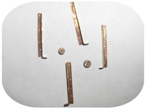
Photo 2 shows “iron” corner pieces that held the sidepieces together. Brass angle iron can be found in most any hobby shop. I had to grind and file these corner pieces, as both sides of the “L” were too large to be in scale. The ends of the corner bars need to be trimmed so you can bend and form feet. Note that there are two lefts and two rights. The pulleys in the photo have no business in this photo and will be explained later.
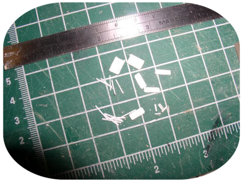
Photo 3 shows the ash pit and firebox access doors and hinge materials. These were made of photo paper, as it is stiff and does not shred, plus it was the right thickness. A sharp pair of scissors or a new number 11 blade in the Xacto knife allows you to get clean cuts on a single pass. Regarding the scissors, if you are friends with your hair stylist/barber or whatever they are called these days, ask him/her for an old pair of small scissors. Pay to get them professionally sharpened if need be. These are great for cutting fine parts, rigging line, etc. without tearing or shredding. (A very good quality NEW pair goes for well over $100US these days.) Even better is to have a doctor friend that can get you a pair of suture scissors. Sorry for the aside on scissors……….back to the tutorial.
These door and hinge parts can be made of brass if your base is made of brass in place of wood. Keep in mind that silver soldering these will be necessary if you use brass. Soft soldering will be too weak. The photo paper stock I chose to use is easily glued to the wood. Obviously they do not open in my stove. Not shown are the hinge pins, which I made from bamboo. I drew down some bamboo through a draw plate to the right diameter then cut them to the proper length. Using wood and paper, gluing was not an issue. If you use brass rod, gluing is an issue. I know some people will say that CA will work, but I am not a fan of CA glue for anything except to hold something in place temporarily for all the reasons bantered about since it came on the market. I suppose epoxy glue would work in this case, but I just don’t like mixing it in such tiny amounts.
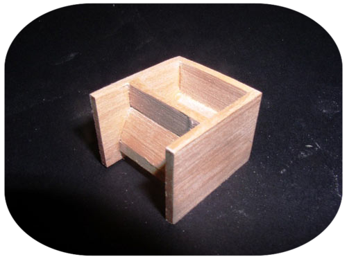
Photo 4 shows the glued up base. It has been coated with wood putty and sanded. This will help hide wood grain on the finished stove.
Photo 5 shows the base again with the top piece. Note that the top piece does NOT extend to the edge of the base, that is, it does not fit flush which can be seen in Photo 6.
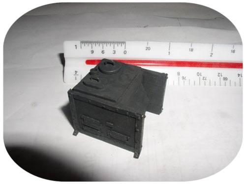
Photos 7and 8 show the parts all assembled and first coat of paint is applied. The cooking pot lids are made and in place in these photos. At some point in the second half of the 18th century, iron pots replaced copper pots on many British ships. If you have copper shim material, some very nice pots can be. Brass was not used, if you are wondering. Note that the one pot was invariably round, and the other a racetrack shape. My lids are made of wood with brass handles. In this photo you can also clearly see the angle iron on the corners. Small brass nails were used to hold these to the base, but I have used brass wire for the bolts in the past. The actual stoves used square head bolts for the most part, but I did not think it detracts too much using the round head nails.
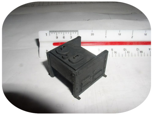
The small round sleeve between the pot lids is a fitting to which a distilling pipe would be attached.
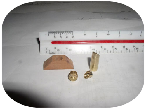
Photo 9 shows the various exhaust parts including the hood and stack, better known as Charley Noble. I do not have any idea how the name came about, but there is a real tradition regarding this piece. I experienced it first hand on my first trip to sea back in 66. The “experienced crew sends the newbie all over the ship looking for Charley Noble. Whenever I asked a crewmember if he had seen Charley Noble, they would send you to the other end of the ship. This went on for several hours before I was let in on the joke. I did not say I was smart, just a little experienced, which comes with time. But I digress………… I turned the brass pieces on the lathe for this stove. Brass tubing can also be used, but the stacks usually tapered thus I turned them on the lathe. There was also a piece between the stack and hood. The stack sat on this stub piece and was able to be turned or removed as needed.
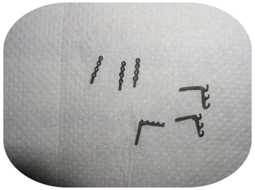
Photo 10 shows a few of the grill support parts that are on the side of the stove opposite the “soup pots” I made these of brass, but I have used stiff card stock coated with glue in the past. The glue does stiffen up the card stock. The brass parts can be cut and filed or etched.
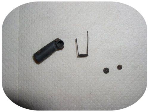
Photo 11 shows the stack silver soldered to give the proper angle at the top. It also shows the damper, which I made of brass. The slide rods are silver soldered to the damper plate, which can be seen in the photo. These rods slide through guides, which will be seen upcoming photos to allow the damper to be adjusted as needed. I don’t know why, but the pulleys are in this photo as well. These will be explained momentarily.
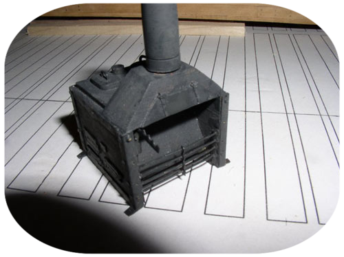
Photo 12 shows the grillwork installed. What cannot be seen clearly are several rods that are near the bottom that lie in a horizontal plane. These lie just behind the vertical rack. I installed these hard to see rods first. Merely drill holes on each side and slip the rods in place. All the rods, with one exception, are 0.020 diameter. All of the brass flat pieces are from 0.010 sheet stock except for the pulleys and damper, which were turned on the lathe. The drip pan was made from 0.005 brass sheet material. For those without a lathe, aircraft plywood should do fine for the damper and pulleys as it will be painted in the end anyway.
In addition to the grillwork, you can see the hood door and its hinges, which were made from photo paper stock and tiny dowels for the hinge pins.
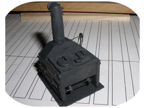
Photo 13 shows the drain valves. I made these on the lathe. The drain pipe then had a small hole drilled in the side to take the valve handles which are no more than small pieces of brass rod that were pounded flat on one end.
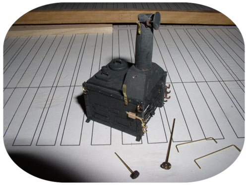
Photo 14 shows the various parts for the rotisserie including the multiple level support arms, pulleys and shafts. On the near side, toward the top is a post that swings. I believe it was used to hang “things” then could be swung towards or away from the heat. At the top of Charley Noble, the damper is assembled and the hinges can be seen. I took this photo before painting to show them a little more clearly.
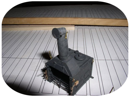
Photo15 shows the lift rings. There were four, one on each corner. I have seen these located toward the bottom of the stove and toward the top of the base in various drawings.
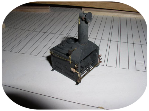
Photo 16 shows the pulleys and side rails from which ladles and such could be hung. These are temporarily installed before blackening. I did blacken most brass parts but wound up painting as well so everything was the same color, if not a little mottled to look old.
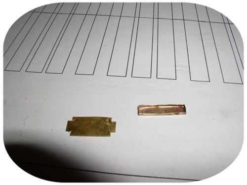
Photo 17 shows the drip pan that sits at the base of the grill area. Mine is made of 0.050 brass sheet as mentioned above. The photo shows a piece that is not yet bent, and second shows it bent and silver soldered. It looks a little beat, but I am sure that was the case on board the real ship.
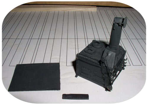
Photo 18 shows the rotisserie pulley chain in place. If I can ever find a small enough (and cheap) jewelry chain or small enough brass chain I will use that, but everything I found was too large to be in scale, so I used black heavy thread for the belt. You can also see the blackened drip pan and “steel base, which is made of aircraft plywood. Not shown are the bare wood slats on which the stove base plate sits. These run athwartships and generally are 4 to 6 in number.
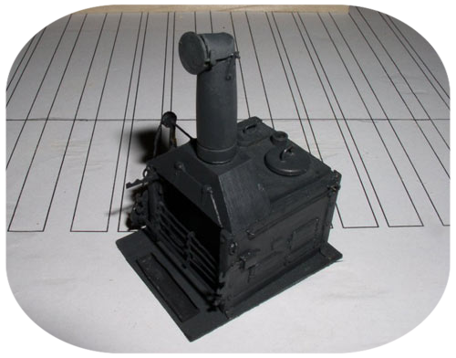
Photo 19 is the finished project ready to install on board and fire up for the boys’ mess.
I am sure I left some things out that were obvious to me, but not to all of you, and please know that it is not intentional, so if there are any questions, ask away.
Allan
Extract by the site http://www.modelshipwrightsdatabase.com